Loading...
Loading...
Loading...
Loading...
Loading...
Loading...
Loading...
Loading...
Loading...
Loading...
Loading...
Loading...
Loading...
Loading...
Loading...
Loading...
Loading...
Loading...
Loading...
Loading...
Loading...
Loading...
Loading...
Loading...
Loading...
Loading...
Loading...
Loading...
Loading...
Loading...
Loading...
Loading...
The web UI is the primary interface for interacting with RoboDot, offering comprehensive control and configuration capabilities from any connected device's web browser. This interface allows users to efficiently manage settings, download data, and monitor various system functions with ease. Meanwhile, the touch screen UI is primarily used to display status information, providing quick and direct access to essential real-time data and system alerts right on the device itself.
The main pages are:
Page
Application
Home
Starting page with quick reference "Field Manual"
Status
Shows position, quality, and state information. Used to set up the base position.
Rover
Enables recording coordinates in to a .sht file
Files
Used to download observations for post process or rover .sht files
Map
Reference map showing RoboDot location.
Positions
A place to save base positions for later use
Settings
Unit configuration
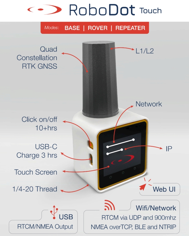
The RoboDot Touch is a portable and versatile GNSS L1/L2 RTK and PPK Base/Rover and Range Extender suitable for RTK mapping with drones, capturing ground control points and GIS applications with cellphone apps. The unit is manufactured by Robota ()
Item
Condition
Value
Run Time
Full Power, full charge
8+ hours
Charge time
Device off
3 hours
Charge current
5v via USB-c
1A
Battery capacity (Li-Ion)
7.2 wH
Wi-Fi Range
Line of sight on 1M pole, iPhone
150 meter radius
Wi-Fi Frequency
2.4 Ghz
Weight
6oz
Size (base)
Without Antenna
2.2 x 2.2 x 2.3 in
Height
With Antenna
4.7 inches
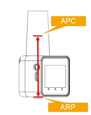
PCO – Phase Center Offset
9.4 cm above base
ARP – Antenna Reference Point
Bottom of RoboDot
Satellite Constellations
GPS, GLONASS, Galileo, BeiDou
Satellite Frequencies Received
Antenna #1
L1/L2, G1/G2, B1, E1
Lora Radio Frequency
If enabled
915mhz
Lora Radio Range
Line of sight - factory antenna
1km
Horizontal Accuracy
10km baseline length
0.01 m + 1 ppm CEP
This site is dedicated to helping our users onboard the RoboDot Touch RTK GNSS into their workflows effectively. We strive to provide comprehensive and easy-to-follow guidance to ensure a seamless integration experience. Your feedback is vital in helping us improve our documentation, ensuring that it meets your needs and expectations. Please don't hesitate to share your thoughts and suggestions, as they will contribute significantly to enhancing the quality and usability of our guides.
Explore the features and functionality of RoboDot Touch. The guide contains all technical "how-to" for the RoboDot device itself.
Learn how to integrate RoboDot Touch into various cases and workflows. It contains contextual "when and why" for RoboDot usage and includes "how-to" for third-party tool integration and workflow-specific procedures.
Updating to this version requires two software update cycles
Say goodbye to the days of deploying separate web devices to manage your RoboDot! The new interactive touch screen UI puts more power directly at your fingertips. Now you can:
Adjust boot settings on the fly
Connect to WiFi or VRS networks instantly
Start and stop recording with a simple tap
Average or Release a base position
Configure many of the settings previously only available on the Web UI
Interface with your favorite GIS and Survey applications more easily than ever before with improved connectivity. A new BLE Rover mode has been created for simplicity and stability.
When RoboDot Connects to the VRS as a client, if there is any disconnection it will automatically atempt to reconnect.
Experience a fresh and snappy web UI that enhances user interaction with modern design and intuitive navigation, providing a seamless experience across all devices.
RoboDots can connect over the internet using RoboNet to deliver RTK corrections.
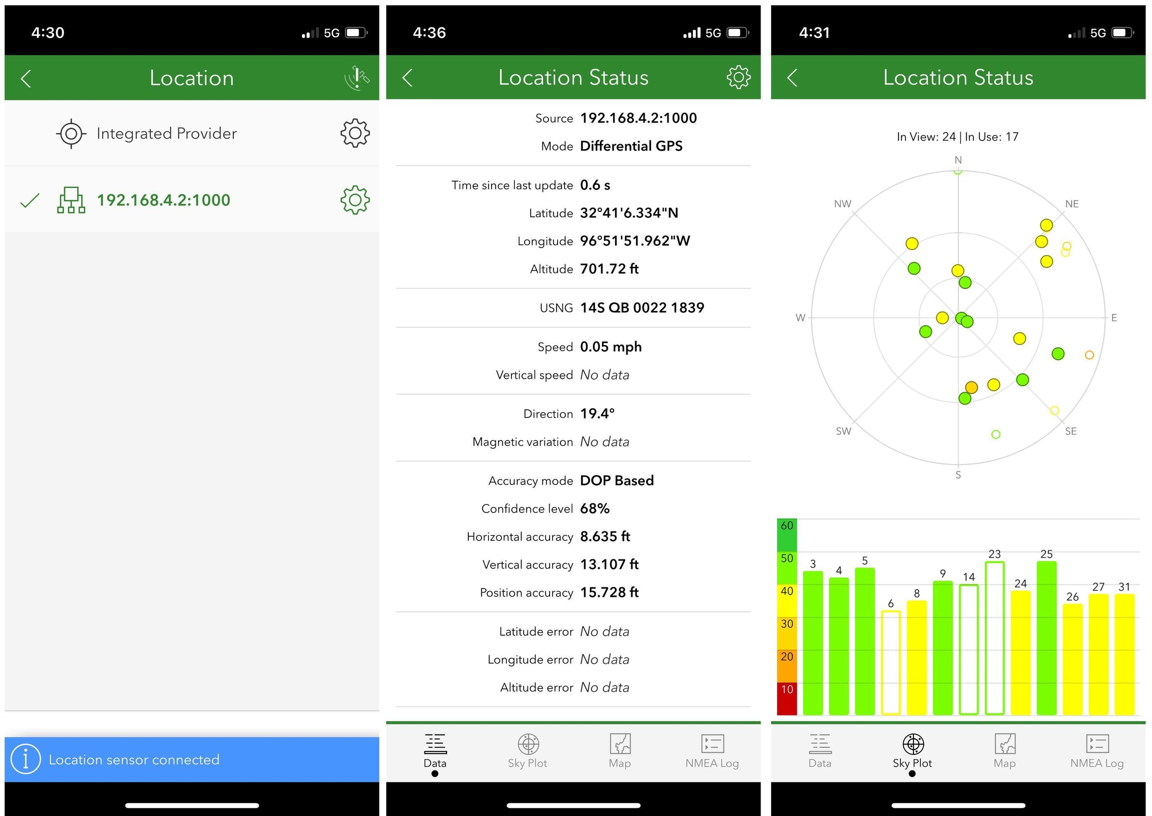
The RoboDot Touch Screen UI is designed for rapid access to the unit's status without the necessity to connect or interface with additional devices or applications.
The Home Screen is the default view when the RoboDot device is powered on. It prominently displays the unit's IP address and status, providing users with an at-a-glance overview of the device's health and connectivity. A QR code is also accessible on this screen, allowing users to quickly load the web UI on a browser, simplifying the process of managing and configuring the device.
The GNSS Screen provides crucial status information related to satellite navigation, including the quality of the fix, which is important for ensuring accurate positional data. A QR code on this screen allows users to simplify the process of copying or sharing position information, making it convenient for note-taking or sharing with others quickly. This feature enhances usability by providing a streamlined method to disseminate vital GNSS data.
The Settings Screen provides a clear interface for users to easily view and modify key settings. This intuitive setup improves efficiency and enhances the overall user experience by making essential controls available quickly without the need to deploy a Web device.
When making changes to settings using toggles or dropdown menus, it is important to note that these changes will not be saved until you press the Home button. Additionally, most setting changes will only take effect upon the next restart. This ensures that users can make multiple adjustments without them being applied immediately, providing flexibility to finalize changes before they are implemented.
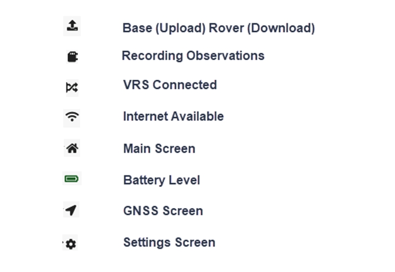
Icons along the top of the touch screen serve as a quick status reference.
RoboDot's flexible connectivity offers Wi-Fi, Bluetooth Low Energy (BLE), USB/Serial and Radio communication options. This ensures flexibility, allowing users to choose wireless or wired connections based on their specific needs. BLE offers quick, energy-efficient communication for low-power applications, while USB/Serial provides a reliable wired alternative for environments where wireless connections may not be ideal.
RoboDot offers flexibility by functioning as either an access point or a station. When operating as an access point, it creates a local network that facilitates device communication without requiring an internet connection. This mode is ideal for local control and data exchange. However, if internet access is necessary, RoboDot can be configured as a station to connect to external Wi-Fi hotspots, thus enabling internet connectivity while maintaining its functionality and integration capabilities.
When devices such as phones, computers, or controllers connect to RoboDot's Wi-Fi network, users can easily access its Web UI for configuration and management. Additionally, the RoboDot supports NTRIP Caster functionality, allowing for seamless real-time kinematic (RTK) positioning data transmission. This setup also facilitates TCP and UDP connections, enhancing network communication flexibility, enabling the integration of third-party applications, and ensuring the efficient flow of data within the local network environment created by RoboDot.
Power on the RoboDot device
Connect via PC or smartphone to Wi-Fi access point RoboDot_### (where ### is the device's unique serial number)
Type the IP address displayed on the main touch screen into a web browser to see the Web UI
No password is required to join RoboDot wifi
Don't use https. Just type the IP address into the address bar.
RoboDot does not provide internet access but does create a local network.
RoboDot Access Point allows for 1 client (Wi-Fi station) to connect at a time.
When RoboDot connects to a Wi-Fi access point such as a hotspot, home, or office network, it gains the capability for internet connectivity, which is crucial for certain functionalities. This method is particularly required when RoboDot engages in activities that require internet access, such as performing firmware updates, accessing VRS correction services, or enabling internet access for other devices that interact with RoboDot.
Connect a device directly to the RoboDot_### Wi-Fi
Use a web browser on your device to navigate to the IP address displayed on the touch screen
Set up hotspot credentials in the settings page under the "Configure" form
Click "connect now" to connect to the hotspot
Enable "Connect on boot" in the settings page for automatic connection on startup for subsequent uses.
Some pages only work properly when the browser has internet access (e.g., Map page, Share page). Internet access is not strictly required for Base/Rover operations.
iPhone can connect directly to RoboDot Wi-Fi while still enabling applications to use data for internet
It's not possible to use internet data on Android while connected to RoboDot Wi-Fi. Connect RoboDot as a Station to the Android device's hotspot for full feature access
To send NMEA from RoboDot to other devices over TCP connection as a Rover, or to send RTCM3 corrections to other devices as a Base:
Enable the TCP Server in the settings page. The TCP server is on port 1000.
To send RTCM3 from RoboDot to other devices via UDP:
Enable UDP output and set your desired port in the settings page.
To send NMEA from RoboDot to other devices over bluetooth use BLE Rover mode.
The USB-C port provides CDC serial communication over USB. In RoboDot versions 3.1.16 and above, serial outputs are set automatically. Per this table:
Mode
Output Type
Base
RTCM3
Rover
NMEA
Repeater
RTCM3
The serial port should be configured to 115200 baud.
The device supports three primary operational modes, which can be set as default boot modes. Users can configure these settings to ensure the device always starts in the preferred mode.
Understanding fix quality is crucial for all operational modes. RoboDot provides several fix quality indicators that represent different levels of positioning accuracy:
Fix Type
Explanation
3D
Standard positioning with 2-meter positioning accuracy. Provides the lowest real-time accuracy but can be post-processed in PPK (Post-Processing Kinematic) workflows to achieve high accuracy results.
Float
Using corrections to try to achieve RTK fix. Typically indicates that the receiver is in the process of converging toward a Fixed solution. In this state, the ambiguities are estimated as floating point numbers.
Fixed
Rover has achieved its most accurate RTK fix. Represents high-precision positioning where carrier phase ambiguities have been successfully resolved to integer values, providing centimeter-level accuracy.
Surveyed
Base has been set on a position, either manually or automatically. Essential in base station modes, where the base requires a predetermined position. Note that this position may not be inherently accurate, depending on how it was obtained. RoboDot allows you to either enter a position manually or average the current readings to establish the surveyed position.
For real-time operations requiring high precision, a Fixed solution is generally desired. For post-processing workflows, collecting data with at least a 3D Fix can be sufficient, as accuracy will be improved during the PPK process.
When operating in base mode, establishing an accurate surveyed position is critical for overall system performance where absolute positioning is desired. The quality of the base position directly affects the accuracy of any rovers using corrections from this base.
The Robodot Touch is equipped with two types of servers: a VRS caster and a TCP Server. The VRS Caster is the most commonly used, providing correction data to rovers when functioning as a base. The TCP Server, on the other hand, offers flexibility by operating either as a rover or a base. When configured as a rover, it sends NMEA data and receives RTCM3 corrections. As a base, it transmits RTCM3 data. It's important to note that only one server can be active at any given time, either VRS Caster or TCP, and users can switch between the two through the settings available in the web UI or the touch screen settings.
Rover mode is utilized for taking point measurements using Real-Time Kinematic (RTK) positioning. For RTK to function effectively, a correction source must be available to provide the necessary data to the rover. This ensures that the rover can determine its position with high precision relative to the base station.
Select "Make Rover" in Web UI status page
Or set boot mode to Rover in Web UI settings page
Navigate to Rover Page for location marking
NTRIP casters over the internet (Virtual Reference Stations VRS)
Lora Radio (Corrections sent over radio from a RoboDot base station)
CORS stations (for postprocessing using PPK Rover Mode)
Corrections over BLE
Corrections over TCP port 1000
Corrections over Serial* (Contact Us)
On the rover page, enter rod height
Optional: Add location identifier
Select "Mark Location"
Points are saved in a shot (.sht) file which is a comma separated file with the following values:
Shot Count
GPS Time
Latitude
Longitude
Height(M)
Quality
Ident
Antenna Offset(M)
Pole Height(M)
Obs Length(S)
Ground Elevation(M)
Sats
PDOP
Reference
Vertical Accuracy(M)
1
2025 02 20 21 42 03
32.68456607
-96.86463903
181.1551
3D
Robota Hanger 7
0.094
1
15
180.0611
23
1.24
Disconnected
1.0406
If the lora radio is enabled in the settings page, RoboDot will receive RTCM3 via Lora from another RoboDot in Base mode on the same frequency, enabling centimeter level precision relative to the base.

RoboDot starts up in base mode by default. It will automatically search for and set an estimated base position if "auto survey" is enabled in the settings page.
Absolute positioning uses a reference point or base station to accurately determine RoboDot's location before starting tasks. This ensures precision by comparing its position with known coordinates, improving the accuracy and efficiency of operations requiring high precision.
Manual Entry:
Enter coordinates in Status Page, Set Position Field
Format: DD.dddd or DD MM SS using
Use negative for south or west longitude
To convert from state plane to degrees, use NOAA's NCAT tool.
Enter pole height
Distance from the ground to the bottom or RoboDot
Select "Set as Entered"
With a VRS Solution:
Manual
Click "Average from GPS" in Status Page, Set Position Field
Position quality depends on the fix quality at hand
Automatic
Enable "Auto Survey" in Web UI Settings
If the base has moved, or to enable a new base position after the base has been surveyed in, use the Set Position form on the Web UI status page select "Release Position".
Alternatively press "Release" in the GNSS touch screen.
RoboDot can send RTCM3 corrections to rovers in these ways:
Over the WIFI network NTRIP caster
Over Lora radio if installed and enabled in the settings page
Over the USB to serial port.
RoboDot allows saving base points for reuse, reducing workload and potential errors during repeated operations at the same locations.
Direct from Survey:
When base station is surveyed in
Click "Save For Later" in status page
Manual Entry:
Navigate to Positions page
Enter and save coordinates directly
Place RoboDot at location
Navigate to Positions page
Select desired position by identifier
Enter pole height (distance from ground to RoboDot bottom)
Click "Set as Base Position"
When a Client/Rover/Drone connects to RoboDot for RTCM3 corrections.
Connect the rover to the RoboDot's Wi-Fi or to the network that RoboDot is on.
Connect the rover to the NTRIP Caster with the following criteria:
Host: As displayed on the RoboDot Touch screen.
Port: 10000
Mount Point: Arbitrary
User: Arbitrary
Password: Arbitrary
Set up hotspot credentials in the settings page Set the RoboDot to automatically connect by selecting "Connect on bootup" Set the credentials to your VRS service Enable your hotspot and restart RoboDot or click connect now under hotspot
When operating as a base, if the LoRa radio is enabled, the RoboDot Touch will transmit correction data to any rovers or repeaters tuned to the same LoRa frequency. This feature facilitates real-time data exchange, ensuring that all receiving devices can benefit from the high-precision GNSS corrections provided by RoboDot.
RoboDot Touch is designed to seamlessly integrate with various systems by automatically outputting RTCM3 data over the USB/Serial connection. This feature ensures that high-precision GNSS corrections can be efficiently transmitted to connected devices without additional configuration.
The LoRa Radio feature is available on the device only if it has been ordered as part of the setup. LoRa facilitates communication between RoboDots over medium distances, reaching up to 1km. This capability not only enhances standard operations but also supports unique applications and workflows. At its most basic, LoRa can establish rover-to-base communications between two RoboDots without requiring an internet connection, thereby providing flexibility in deployment and operation. The LoRa radio applies in Base, Rover and Repeater modes.
Range: Up to 1km line-of-sight
Automatically transmits RTCM3 in Base mode
Automatically receives corrections in Rover mode
Frequency: 915MHz (factory default)
Connect the 900mhz antenna to the rear of the Robodot Touch
Enable/disable in the Web UI settings page
As a repeater RoboDot will receive corrections over LoRa and make those available over the local NTRIP caster thereby extending correction range up to 1km between base and rovers.
Enable Lora radio in settings
Select repeater as boot mode
Restart device
Device maintains repeater function until boot setting changes
Two RoboDots minimum
Both need LoRa radio capability on the same channel
One requires repeater functionality
Maintain single base reference with lora enabled
Connect a rover to a repeater's NTRIP
One of RoboDot's main features is its capability to record GNSS observation data, which can serve as both a backup and a primary source for post-processing workflows. This is especially useful for ensuring data integrity and accuracy during field operations. The recording activity is confirmed via a green indicator light, and users can also verify the status through the Web UI or the touch screen display. This dual confirmation method enhances the reliability of data recording, making it an essential tool for GNSS data collection and management.
Filename format: dot###m#d#y#h#m#s#gpst (in GPS time indicating the start date of the record)
The observation file extension is .rub. It should be converted to RINEX using the RoboDot Utility Software or via Wingman Tools online portal.
The RoboDot device offers flexible recording trigger options to accommodate various user needs. First, the Auto-start feature with "Record on Boot" enabled allows recording to commence automatically once a GNSS lock is acquired, ensuring seamless data capture without manual intervention. This is particularly advantageous in scenarios where immediate data recording is crucial.
Alternatively, users can exercise manual control over the recording process through the Rec/Stop button available on the Status and Rover web pages, providing more granularity and control to the operator. These options make the device versatile and adaptable to different operational demands.
Rover Mode creates an additional .sht file which is a csv file with details on each point recorded. Learn more in the Rover Mode section.
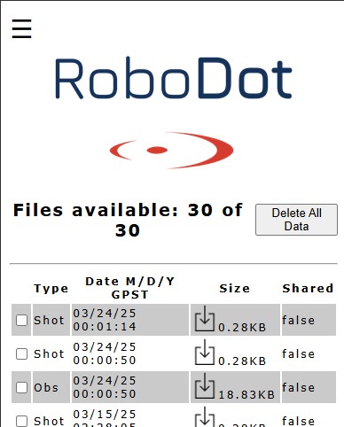
To download project files, access the Web UI and navigate to the Files page. There, you can download files such as .rub and .sht for further processing or analysis. These files can also be shared with Wingman to facilitate company-wide use, streamlining collaboration and ensuring all team members have access to the necessary data.
Location: Web UI, Files Page
File types:
.rub: Raw observations
Convert to RINEX for post-processing with RoboDot Utility
Used in post processing workflows
.sht: Position data (Rover mode)
Contains rover shots generated by "Mark Location"
Also created for base points
Comma separated text file.
In the Files Page, files can be uploaded to the Wingman portal by selecting the desired file and clicking "share files". Follow the instructions on the share page.
Wingman can email you a copy of the file and submit observation files to Opus.
See the hardware asset in the Wingman Dashboard at www.robota.us to configure the desired behavior.
The antenna phase center (APC) is located 9.4cm (0.094m) from the bottom of the RoboDot.
This distance is available on the RoboDot Touch Screen settings page.
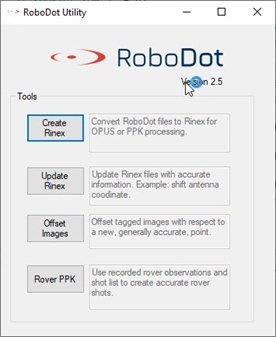
RoboDot Utility is a set of handy tools for post processing. Download it via Wingman
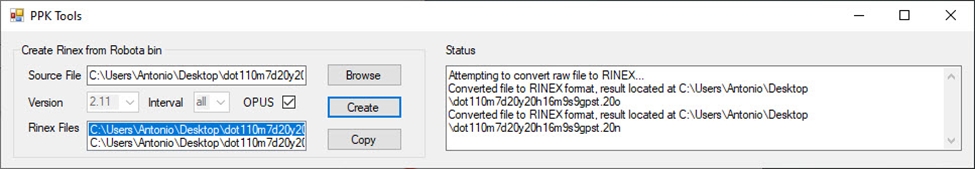
Convert RoboDot .rub observation files to RINEX
Correct Rinex File Antenna Position
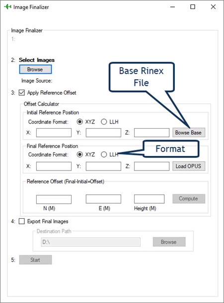
Offset Image Coordinates
Post Process Rover Positions
Download the .rub file from RoboDot
Browse for the .rub file
Click "Create" to generate observation files
Two file types are generated:
*_opus.o: GPS-only format for OPUS submissions
*_all.o: All constellations for other processors
Obtain the accurate position of the operating point using a post processor like OPUS, NR-CAN or AUSPOS then use the offset image tool to shift imagery to the correct reference point.
Download observation files from the RoboDot (RUB format)
Convert the files to Rinex
Upload the Rinex to a PPP service like OPUS
Launch the tool and populate the original Rinex file plus the OPUS result
Start the process optionally selecting a new output directory.
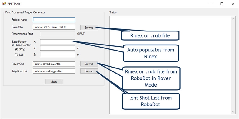
When the RoboDot is used as a PPK rover, it must be recording observation data. When a location is marked on the shot list page, a new .sht file is created. Both of the rover’s .rub and .sht files need to be downloaded and applied to the PPK Rover tool. A base observation file must be obtained from a second RoboDot or alternate base station. When the tool has completed the process, a new .sht file is created with corrected position data.
Download rover's .rub and .sht files.
Obtain a base observation file.
Apply files to the PPK Rover tool
*Internet access is required for orbit data download in version 2.4.10 and below.
To power on: Depress the main switch on the side of the RoboDot for half a second.
The unit will vibrate and beep and show a solid blue LED.
To power down: Click the same button for a fraction of second. The button is only responsive once the unit is done booting up.
The unit will vibrate, beep and flash the red LED.
If the unit were to become unresponsive, holding the power button for 4 seconds forces it to turn off.
Charge the device using a USB 3.0 port with 1A capability and a USB-C cable. It takes 3 hours to reach a full charge. The unit can be charged during use, and it will charge regardless of being on or off. When the charger is connected, the RoboDot will automatically turn on.
Charge is complete when the bolt on the battery indicator is off.
Only use approved chargers that are delivered with RoboDot
A status LED is available in addition to the touch screen and web UI. It provides a quick reference to the state of the RoboDot from a distance.
Color Code
Meaning
Blue Solid
Booting
White Blink
No GPS
Yellow Blink
Not recording
Green Blink
Recording Observations
Blue Alternating
Unit is connected to VRS
Orange Alternating
Unit is receiving corrections via LoRa
Red
Memory card failure
For the best user experience, register your RoboDot one Wingman before getting started. Registration is required for:
Warranty service
Firmware updates
RoboDot Utility downloads
Wingman Online Tools
Follow the steps at the URL indicated on the boot screen. Register the RoboDot with the serial and key displayed on the boot screen.
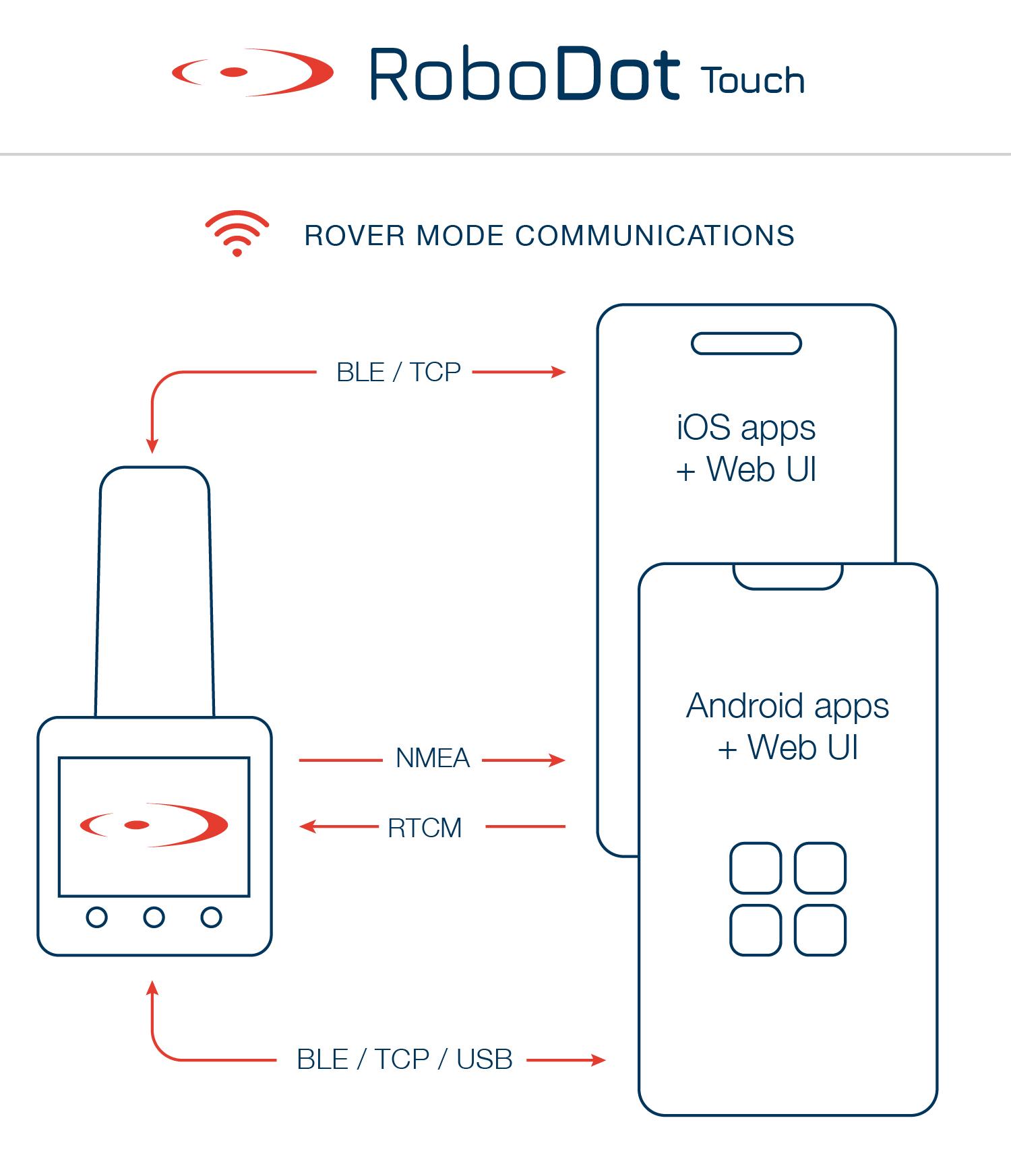
BLE rover mode is utilized when the RoboDot Touch is intended to operate with BLE applications. In this mode, the WiFi access point and web UI are disabled, restricting access to these features. To exit BLE rover mode, one must change the boot mode through the touchscreen settings page.
When BLE rover mode is active, your app should connect to the Touch_### advertisement to establish communication.
In BLE rover mode, Android OS typically requires devices to first pair with the smartphone before establishing a connection. This step involves navigating to the Bluetooth settings on the Android device, locating the RoboDot Touch, and completing the pairing process. In contrast, iOS devices do not display the RoboDot Touch in the Bluetooth menu for pairing. Instead, the iOS application utilizes the Core Bluetooth framework to discover and connect to the device directly, streamlining the communication process without the traditional pairing steps.
In BLE rover mode, the RoboDot Touch outputs NMEA data over the Nordic UART characteristic, which serves as a key communication channel for transmitting standardized GPS data to connected applications. Meanwhile, it also supports the reception of RTCM3 correction streams, which enhances the accuracy by providing differential GPS correction data. This integration ensures that the RoboDot Touch maintains high precision in its positioning data, essential for applications requiring reliable and accurate location services.
The RoboDot Touch firmware can be updated over the internet. It is recommended to regularly update your device to ensure you have access to the latest features and fixes. Here’s how you can update your RoboDot:
Connect RoboDot as a Station to the internet via a hotspot or office network.
Click "Get Updates" under the about section in the settings page.
When the Updates page loads click, "Software Update"
Wait for the update process to complete and reboot the RoboDot.
Note: Older units may need to be mailed in for updates.
Variant
Feature
RBT_RDT
Full features without lora radio
RBT_RDT2
Adds lora radio for Rover/Base operations
RBT_RDT3
Adds lora radio for Rover/Base/Repeater operations


RoboDot carries a 12-month warranty from date of purchase. For warranty repairs contact Robota via contact form at https://www.robota.us/. With an RMA request complete ship to:
Robota LLC 5015 Voyager Dr #7 Dallas, TX 75237
Orange colored RoboDot's dont have serial in capability. This feature was added later with the white colored RoboDot.
Obtaining IP address message on Wi-Fi connection
First connect RoboDot to the controller then turn the drone on.
Long Convergence Time
Base is not in "Surveyed" in Fix Type. Click Survey or "Average from GPS"
The set position is not accurate enough, click "Release Position" and Survey again
The base or rover don't have a clear sky view
Short LoRa Radio Range
Ensure that both units have antennas on them.
Both units should be elevated from the ground
Obstructions can minimize range

Reference this Youtube on different ways to place the RoboDot.
The RoboDot's physical placement is crucial for optimal operation:
Requires unobstructed sky view for satellite reception
Must be stable and secure as a base station
For absolute referencing workflows, must maintain consistent position over a specific point
Uses 1/4-20 thread for photography/lighting tripods
Ideal for elevating device in relative positioning modes
Requires adapter for 5/8-11 surveying poles
Recommended: Surveying bipods/tripods for known point positioning
Magnetic mounts available for vehicle attachment
Note: Vehicle movement can affect operation
Not recommended for precision work
Direct ground placement possible
Use stencil to mark operation point for reference
Fix quality is an indicator of the accuracy of the GNSS estimate. When seeking the highest accuracy as a rover, expect to see a fixed indicator on the UI. When operating as a base, the base must be Surveyed for the rover to obtain a fixed status.
RoboDot offers a range of applications, prominently featuring its integration with drones as a local RTK base station, eliminating the need for an internet connection while providing very short baselines. Additionally, RoboDot supports long-range operations through its repeater mode. It facilitates the collection of ground control points in three different methods, allowing for versatile and adaptive workflows that can be combined based on specific application requirements.
Flying drones with RTK GPS has benefits in surveying and navigation. When surveying, images will be geotagged with accurate images relative to the base position.
First connect the controller to the RoboDot wifi, then connect or configure the Custom RTK network in the controller. Use the following credentials:
Host: The IP on your RoboDot screen, typically 192.168.4.2
Port:10,000
Mount Point: X
User: X
Password: X
Reference this YouTube for an example with the DJI M3E.
Drone controllers with web browsers can be used to access the Web UI.
Accurate image geotagging
Enhanced navigation
Local base advantages over online VRS
Relative Positioning:
Place RoboDot
Connect drone controller to RoboDot Wi-Fi
Use Auto Survey or Average from GPS
Absolute Positioning:
Follow relative steps
Add base position coordinates
Option: Connect via shared access point
Shifting:
Operate under Relative Positioning steps
Post flight shift images using RoboDot Utility
When a project's scope is too vast to be managed from a single point, mobility around the site becomes beneficial. However, relocating a local base station and re-establishing it at a new site can be cumbersome. Moreover, moving the base station may introduce errors into the project. Therefore, it is often better for all rover and drone data to refer back to a single base point. In such instances, RoboDot can be utilized in Repeater mode to increase the operational range to up to 1km.
Reference this Youtube on how Repeater mode works.
Ground control points are commonly used in photogrammetry for map correction and referencing. GCP coordinates can be obtained in many ways including:
Example: RTK Flight with GCP Collection post flight
Follow the RTK drone integration steps
Complete drone flight
Select the appropriate Base Reference:
Single RoboDot options:
Switch to Rover Mode with VRS
Record the Rover observations for PPK processing
Dual RoboDot option:
Use a second RoboDot as Rover with Lora Radio to reference the base
Collect GCPs with the Rover
Geographic Information Systems (GIS) have traditionally relied on low-accuracy GNSS for creating map layers. Nowadays, users can opt for centimeter-level accuracy with RTK GPS, which has become more affordable and is in demand for precise projects. Consequently, RoboDot is a viable option for cost-effective and accurate GIS operations.
NMEA sentences are transmitted from RoboDot to GIS applications through TCP, Bluetooth (LE), and Serial connections.
RoboDot should be set up as a Rover when used with GIS and Surveying applications
RoboDot expands its functionality by interfacing with a multitude of device applications to replace their internal, often inaccurate GPS systems. Through robust connectivity options like Bluetooth Low Energy (BLE), Serial, and TCP, RoboDot offers versatile integration possibilities. For instance, popular GIS and surveying apps can effortlessly connect via these protocols to leverage RoboDot's centimeter-level accuracy, enhancing the overall mapping precision. Many applications share similar integration interfaces, ensuring that RoboDot can seamlessly maximize operational potential across various devices, whether through a WiFi network, BLE, or Serial connections.
License Grant: This product includes software that is licensed, not sold, to you by Robota LLC. You are granted a non-exclusive, non-transferable license to use the software solely with the associated hardware.
Restrictions: You may not (i) copy, modify, or distribute the software; (ii) reverse engineer, decompile, or disassemble the software; (iii) use the software for any illegal purposes.
Ownership: The software and all related intellectual property rights remain the property of Robota LLC. This license does not transfer any ownership rights to you.
Limitation of Liability: Robota LLC shall not be liable for any damages arising from the use of this product beyond the purchase price of the product. By using this product, you agree to the terms of this EULA.
You may transfer your rights under this End-User License Agreement (EULA) to another party only if you transfer the device, the software, and all accompanying documentation, and provided that the receiving party agrees to the terms and conditions of this EULA. Upon such transfer, you must cease all use of the software and remove any copies installed on your devices. You must notify Robota LLC of the transfer to ensure the new owner’s rights and access to updates and support.
This End-User License Agreement (EULA) is only valid for individuals who have lawfully obtained the device and accompanying software. Any use of the device or software obtained through illegal means, including theft, is strictly prohibited and constitutes a violation of this agreement and applicable law. Robota LLC reserves the right to disable or limit functionality of the device and software if it is reported stolen, and will cooperate with law enforcement authorities to recover the stolen property and pursue legal action against the perpetrator.
This device complies with Part 15 of FCC rules. Operation is subject to the following two conditions: (1) this device may not cause harmful interference and (2) this device must accept any interference received, including interference that may cause undesired operation
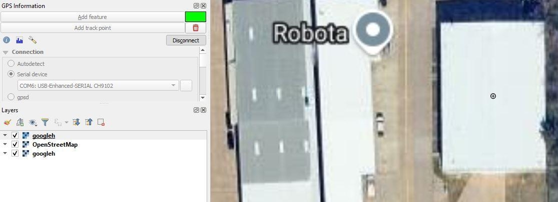
RoboDot interfaces with QGIS to ensure precise GPS coordinate tracking by integrating its output with QGIS's mapping capabilities. By connecting RoboDot to a PC through the specified serial port setup, users can seamlessly transmit GPS data to QGIS. This connection allows for real-time marking and plotting of points on geographic maps, enhancing accuracy in spatial data representation. This integration transforms RoboDot into a powerful tool for geographic analysis and precise location pinpointing, leveraging QGIS’s sophisticated GIS tools.
Connection: Serial port Setup:
Connect via USB
Configure GPS panel:
Select serial device
Choose COM port
Connect
For the highest accuracy in your RoboDot setup, enable it to connect to a Wi-Fi hotspot and a Virtual Reference Station (VRS) for corrections. This configuration facilitates Real-Time Kinematic (RTK) level precision, significantly enhancing the positional accuracy beyond what is possible with standard GPS alone. By leveraging these network connections, RoboDot can achieve highly precise geolocation data, essential for tasks requiring exact positioning.
SW Maps GIS, a free mapping application, integrates real-time GNSS data for precise field collection across surveying, agriculture, and environmental projects. When paired with high-precision systems, it enables reliable data collection that improves decision-making and resource allocation.
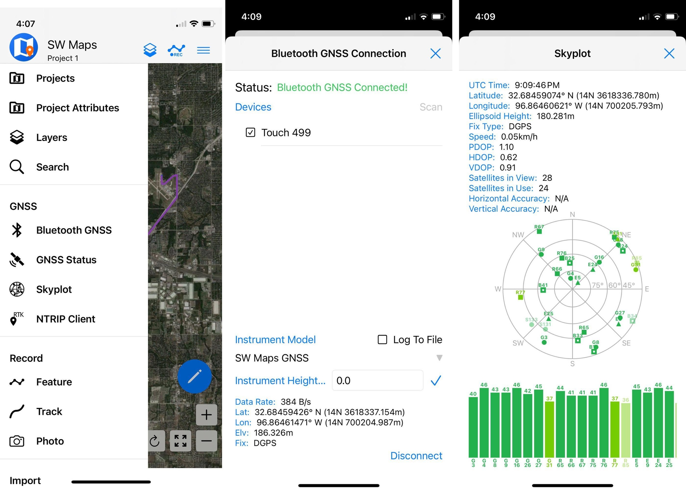
SW Maps for iOS has streamlined the process of integrating with high-precision GNSS devices by exclusively supporting Bluetooth Low Energy (BLE) connections to RoboDot.
Enable RoboDot Bluetooth in Web UI settings
In SW Maps menu, select Bluetooth GNSS
Select the Touch_### and connect to device as "GENERIC NMEA"
Click NTRIP Client to configure a correction service for high accuracy
Do not set up RoboDot to connect to a VRS, the app proviedes the corrections
In this configuration, the RoboDot (acting as a rover) connects to the iOS device using Bluetooth Low Energy (BLE). The iOS device, which generally has internet connectivity, then connects to the Virtual Reference Station (VRS) to receive RTK corrections. These corrections are subsequently relayed back to RoboDot, enabling it to achieve precise positioning accurate enough for applications that demand higher location precision.
SW Maps GIS is a free mapping application that integrates real-time GNSS data for accurate field collection. When coupled with high-precision GNSS systems, it delivers reliable location data essential for surveying, agriculture, mining, construction, and environmental projects, minimizing errors and improving resource allocation across professional applications.
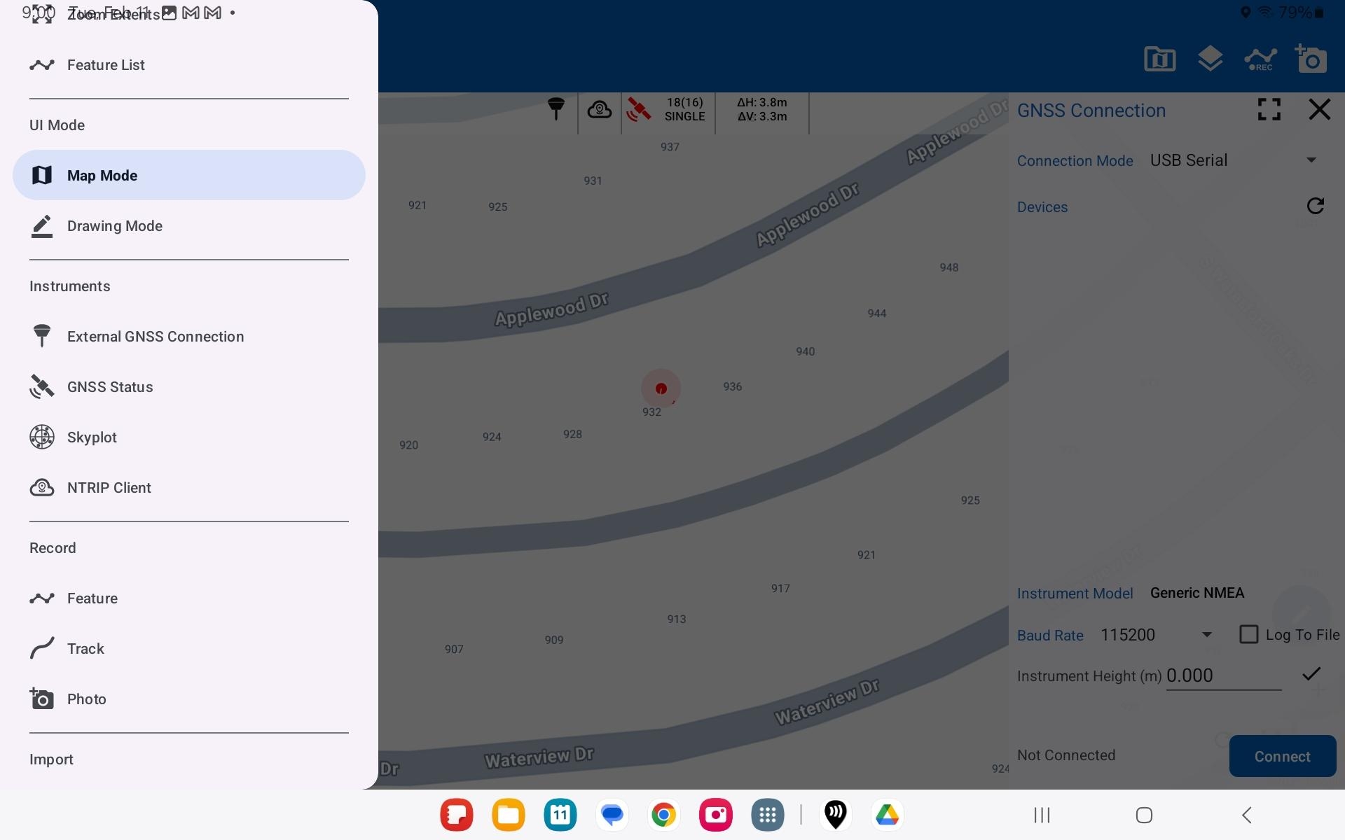
SW Maps for android offers two connection methods for integrating with RoboDot, Serial or Bluetooth LE.
Unlike the iOS version, the Android version of SW Maps offers the flexibility of establishing a serial connection as well as Bluetooth Low Energy (BLE) for integrating with devices like RoboDot. This additional connection option often requires a USB-C to USB-C cable, allowing users to connect directly via USB Serial. Depending on your specific requirements, you can choose between the high-speed reliability of a serial connection or the convenience of wireless BLE. Choose the method that best aligns with your device compatibility and operational needs.
While SW Maps offers robust connectivity options such as direct serial and Bluetooth Low Energy (BLE) connections, it can also be used alongside the GNSS Master application for enhanced functionality. Integrating with GNSS Master may provide additional connection methods. However, utilizing GNSS Master is not essential.
Select External GNSS Connection
In connection mode, select USB Serial
Set baud rate to 115200
Enable RoboDot Bluetooth in Web UI settings
Pair RoboDot Touch with the device first via android settings
In SW Maps, select External GNSS Connection
In connection mode, select BLE
Select paired RoboDot device and connect using "Generic NMEA"
Finally configure the NTRIP Client in SW Maps
In this configuration, the RoboDot (acting as a rover) connects to the Android device using Bluetooth Low Energy (BLE) or Serial. The Android device, which generally has internet connectivity, then connects to the Virtual Reference Station (VRS) to receive RTK corrections. These corrections are subsequently relayed back to RoboDot, enabling it to achieve precise positioning accurate enough for applications that demand higher location precision.
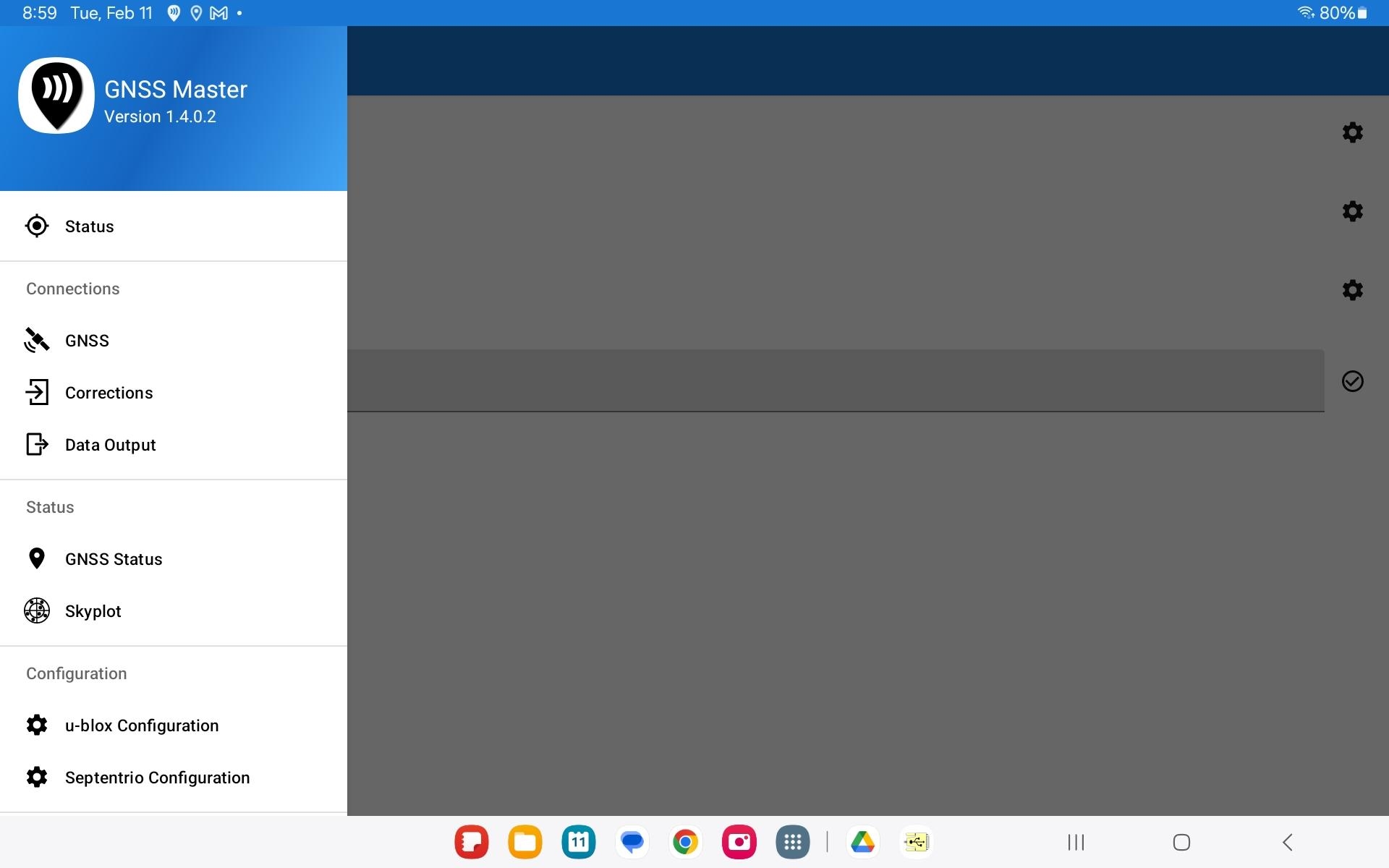
GNSS Master enables any Android app using GPS to access RoboDot's high-accuracy positioning. Android apps that do not support external GNSS natively but can work with GNSS Master include:
ArcGIS Field Maps
Google Maps
Apglos
Google Earth
Avenza Maps
KML/GPX tracking apps
Matidor
Most navigation and mapping apps using Android location services
Install GNSS Master
Enable Developer Mode on Android device
In Settings, About: Find "build number"
Tap "build number" several times
Turn on Mock Location setting
Find the newly created Developer Options in Settings
Look for "Allow mock locations" or "Select mock location app"
Select GNSS Master as location source
Run GNSS Master and your GIS application
Under Status
Turn on Mock Location slider
Under Connections, GNSS, select and connect the preferred an input source:
Serial
115200 baud
TCP
Use the IP on RoboDot screen, Port 1000
BLE
Under Connections, Corrections, configure and connect the correction source:
Typically an internet based VRS
In this configuration, the RoboDot outputs GPS data to the Android tablet, effectively using the tablet as a relay for data communication. The tablet is responsible for sending RTK corrections back to the RoboDot, functioning as a rover. Leveraging its internet connection, the tablet connects to the VRS (Virtual Reference Station) to acquire the necessary corrections, ensuring high accuracy in positioning. This setup allows the RoboDot to operate without requiring its own direct internet connection, as all data transmission and correction management are handled through the tablet.
QField is an open-source mobile GIS application that extends QGIS functionality to field data collection on Android, iOS, and macOS devices. When paired with RoboDot Touch RTK GNSS receiver, QField delivers centimeter-level positioning accuracy through TCP connectivity, enabling precise geospatial data capture for professional applications. This integration makes high-precision mapping accessible and efficient, with RoboDot providing real-time kinematic positioning while QField offers intuitive data collection interfaces and seamless synchronization between field and office environments.
The QField device must be on the same network as the RoboDot for this connection to work.
Setup RoboDot to boot as a Rover
Connect RoboDot as a Station to a Wi-Fi hotspot and connect to correction source.
Enable RoboDot TCP server in the Web UI settings page or touch screen settings.
In QField , configure the positioning device:
Under Settings, Positioning
Use RoboDot IP displayed on the screen
Use Port 1000
Primary function for establishing accurate survey points. Two workflow options:
Secure point before additional operations
Use for drone mapping/rover shot baselines
Begin operations immediately
Determine point later via PPP
Adjust previously acquired coordinates
Use RoboDot Utility with Image Offset Tool
When collecting GCPs or surveying a point ahead of rover operations.
Collect minimum 2 hours of observations at control point
Submit rinex file *_opus.o to NOAA's OPUS with:
Antenna type: NONE
Height: Pole height + 0.094m to get the ground elevation
RoboDot provides Real-Time Kinematic (RTK) positioning in two accuracy types:
High accuracy relative to base station
Suited for local survey work
Does not require absolute coordinates
Requires known point coordinates
Reference options:
Pre-surveyed point
Real-time corrections from:
Another positioned RoboDot
Virtual Reference Station (VRS)
Applications include:
Ground control point marking
Check shots
Point surveying
Geographical Information Systems
Considerations
Terrain and obstructions that may reduce effective range
Testing range before critical operations is recommended
Applications include:
Large area mapping
Operations with line-of-sight limitations
Operations that require multiple simultaneous rovers from a single source
Drone mapping while collecting GCPs
Survey123, an ESRI GIS app, offers robust data collection and analysis capabilities with seamless integration across the ESRI ecosystem. When combined with RoboDot, this solution enhances geospatial accuracy by improving feature and point referencing, enabling precise data collection for professional decision-making applications.
Survey123 for iOS enhances geospatial data accuracy by allowing users to replace the device's internal GPS with a more precise external source via TCP connections. This feature enables connection to systems like RoboDot, ensuring highly accurate location data, which is crucial for precision in professional applications.
The Survey123 device must be on the same network as the RoboDot for this connection to work.
Enable RoboDot TCP server in the Web UI settings page or touch screen settings.
In Survey123, configure the provider provider:
Select "Network Connection"
Use RoboDot IP displayed on the screen
Use Port 1000
For VRS corrections to RoboDot
Set up the hotspot on RoboDot and connect to it
Seet up the VRS on the RoboDot and connect to it
In this configuration, Survey123 will attempt to establish a connection with RoboDot Touch over TCP to facilitate advanced geospatial operations. When RoboDot has internet access, it can connect to a Virtual Reference Station (VRS) to enable Real-Time Kinematic (RTK) Fixed modes for superior accuracy. As Survey123 does not include an NTRIP client, users must utilize the RoboDot NTRIP client instead. To achieve optimal positioning accuracy, ensure RoboDot is connected to the internet and properly configure a VRS. This setup enhances data precision, supporting critical decision-making tasks with reliable geospatial information.
Aerotriangulation is a photogrammetric method of determining the geometric properties of objects from photographic images, especially for mapping and modeling purposes.
The point in an antenna where the GNSS signal is considered to be received, crucial for precise positioning calculations.
A Base Station is a GNSS antenna and receiver set up as a reference specifically to collect data to be used in determining precise rover positions.
In GNSS surveying, the vector distance between two GNSS receivers simultaneously tracking the same satellites.
A global navigation satellite system developed and operated by China, providing positioning, navigation, and timing services.
Building Information Modeling is a process involving the generation and management of digital representations of the physical characteristics of sites.
Building Information Models are digital models that support decision-making regarding a built asset.
Computer-Aided Design is the use of computers in the creation, modification, analysis, or optimization of a design, typically used in reference to 3D modeling of physical objects.
A set of data points in space produced by 3D scanners or photogrammetry, representing the external surface of an object or terrain.
A point on the ground with known coordinates used to georeference and align spatial data accurately.
Continuously Operating Reference Stations are networks of GNSS receivers that provide real-time correction data and support high-accuracy positioning.
A Digital Elevation Model is a 3D representation of a terrain's surface created from terrain elevation data, excluding objects like buildings and vegetation.
An indicator of the quality of a GNSS position considering the geometry of the satellite constellation relative to the GNSS receiver. A low DOP value is preferred. Common DOP types are:
GDOP - Geometric Dilution of Precision considers the combination of vertical, horizontal, time, and position errors.
HDOP - Horizontal Dilution of Precision represents the effect of satellite geometry on horizontal position accuracy.
PDOP - Position Dilution of Precision combines the horizontal and vertical DOP.
RDOP - Relative Dilution of Precision measures the relative positional error between two receivers.
TDOP - Time Dilution of Precision represents the effect of satellite geometry on time determination accuracy.
VDOP - Vertical Dilution of Precision represents the effect of satellite geometry on vertical position accuracy.
A Digital Surface Model is a 3D representation of the Earth's surface, including all objects on it, such as buildings, trees, and other structures.
A Digital Terrain Model is similar to a DEM but includes additional terrain attributes, such as break lines and mass points, to represent the ground surface more accurately.
Earth-Centered, Earth-Fixed is a Cartesian coordinate system used by the WGS‑84 reference frame. In this coordinate system, the origin is at the Earth's center of mass.
European Geostationary Navigation Overlay Service is a regional satellite-based augmentation system that improves the accuracy of GNSS signals over Europe.
A mathematically defined surface that approximates the shape of the Earth, used as a reference in geodesy and map projections.
Information about the positions and velocities of GNSS satellites, used by receivers to calculate accurate positions.
Indicates that the integer ambiguities have been resolved, providing the most precise type of solution available in an RTK GPS application.
Indicates that the integer ambiguities have not been resolved, resulting in positional accuracy less than that of a fixed solution.
A global navigation satellite system controlled by the European Union.
An easily identifiable point on the ground that can be used as a reference for measurements. Ground control points are often used in surveying and photogrammetry to provide a known reference point.
The process of converting addresses or other location descriptors into geographic coordinates.
A database designed to store, query, and manipulate geographic information and spatial data.
A coordinate system and reference points used to locate places on the Earth, serving as a foundation for mapping and surveying.
The hypothetical shape of the Earth, coinciding with mean sea level, used as a reference surface from which to measure elevations.
The process of assigning real-world coordinates to each pixel of a raster image or vector dataset, aligning spatial data to a known coordinate system.
A Geographic Information System is a system that collects, stores, analyzes, and displays geographically referenced information.
Global Navigation Satellite System is the GNSS controlled by the Russian government.
Global Navigation Satellite System is the standard generic term for satellite navigation systems that provide geospatial positioning with global coverage.
Global Positioning System is the GNSS controlled by the U.S. government.
Ground Sampling Distance is the distance between pixel centers measured on the ground, representing the spatial resolution of an aerial image.
Horizontal Dilution of Precision represents the effect of satellite geometry on horizontal position accuracy.
An Inertial Measurement Unit is a device that measures and reports a body's specific force, angular rate, and sometimes the magnetic field surrounding the body, using a combination of accelerometers and gyroscopes.
A method of surveying where the GNSS receiver is in motion, allowing for rapid data collection over large areas.
The primary L‑band carrier used by GNSS satellites to transmit satellite data on the 1575.42 MHz frequency.
The secondary L‑band carrier used by GNSS satellites to transmit satellite data on the 1227.6 MHz frequency.
Light Detection and Ranging is a remote sensing method that uses laser pulses to measure distances to the Earth's surface, generating precise, three-dimensional information about the shape of the Earth and its surface characteristics.
A systematic transformation of latitudes and longitudes from the Earth's curved surface onto a flat plane.
An error in GNSS signal reception caused by signals reflecting off surfaces before reaching the receiver, leading to inaccuracies.
North American Datum 1983 is a geocentric datum and reference system used for geodetic control in North America.
The National Marine Electronics Association defines a standard data format for interfacing marine electronic devices, commonly used by GNSS receivers to transmit data.
Networked Transport of RTCM via Internet Protocol is a standard method for RTK GPS rovers and base stations to exchange correction data over the internet.
Online Positioning User Service provides free post-processing of GPS base data into high-accuracy National Spatial Reference System coordinates.
An orthomosaic is a geometrically corrected and georeferenced aerial image composed of multiple photographs stitched together to create a seamless and accurate map.
Position Dilution of Precision combines the effects of HDOP and VDOP to represent the effect of satellite geometry on three-dimensional position accuracy.
Points identified on overlapping images used to stitch images together in photogrammetry, ensuring accurate alignment.
The science of making measurements from photographs, especially for recovering the exact positions of surface points.
Post-Processed Kinematic is a GPS correction technique where the correction calculations are performed after data collection, rather than in real-time like RTK.
Precise Point Positioning is a GNSS data processing technique that provides highly accurate position solutions without the need for a local reference station.
A measure of how closely repeated measurements or observations under unchanged conditions show the same results, indicating the repeatability of one or a set of measurements.
Relative Dilution of Precision measures the relative positional error between two receivers.
Receiver Independent Exchange Format is a file format that is commonly used to interchange raw satellite navigation system data.
In GNSS surveying, a mobile receiver unit that collects data while moving, receiving corrections from a base station or network.
Radio Technical Commission for Maritime Services defines the RTCM protocol that high-precision GPS receivers use to exchange correction data.
Real-Time Kinematic is a technique that uses carrier-based ranging to provide ranges to satellites that are much more precise than those available through code-based positioning.
Real-Time Network is a network of GNSS reference stations that provide real-time corrections over a wide area, enhancing positioning accuracy for rovers.
A recording of satellite signals made using GNSS receivers for later processing.
Satellite-Based Augmentation System enhances GNSS signals by providing correction messages, improving accuracy, integrity, and availability.
Smoothed Best Estimate of Trajectory is data output from inertial measurement units (IMUs) combined with GNSS data to provide accurate position and orientation information.
Structure from Motion is a photogrammetric technique that reconstructs 3D structures from 2D image sequences by estimating camera positions and orientations.
Signal-to-Noise Ratio is a measure of signal strength relative to background noise, important in assessing the quality of GNSS signals.
A surveying technique where the GNSS receiver remains stationary for a period, providing high-precision position data.
Time Dilution of Precision represents the effect of satellite geometry on time determination accuracy.
The mathematical process of converting coordinates from one coordinate system to another.
The slowing of GNSS signals as they pass through the Earth's troposphere, causing delays that can affect positioning accuracy.
An Unmanned Aerial Vehicle is an aircraft without a human pilot onboard. In surveying and mapping, UAVs are often used to collect aerial imagery and data for analysis.
Universal Transverse Mercator is a coordinate system that divides the world into a series of six-degree longitudinal zones, allowing for detailed mapping.
Vertical Dilution of Precision represents the effect of satellite geometry on vertical position accuracy.
World Geodetic System 1984 is the mathematical ellipsoid used by GPS since January 1987.
Web Map Service is a standard protocol for serving georeferenced map images over the internet.
To access our comprehensive customer support, register at www.robota.us for the Wingman portal. This platform enables hardware tracking, provides download resources, offers various tools, and supports file sharing and processing.
To enable downloads, first sign up, then register your product by adding hardware in the dashboard.